7 Dangerous Electrical Wiring Shortcuts to Avoid
Performing your own electrical work around your home can be rewarding, as long as you are careful to follow codes and best practices. Many wiring jobs require a permit because the homeowner isn’t expected to know the ins and outs of the National Electrical Code.

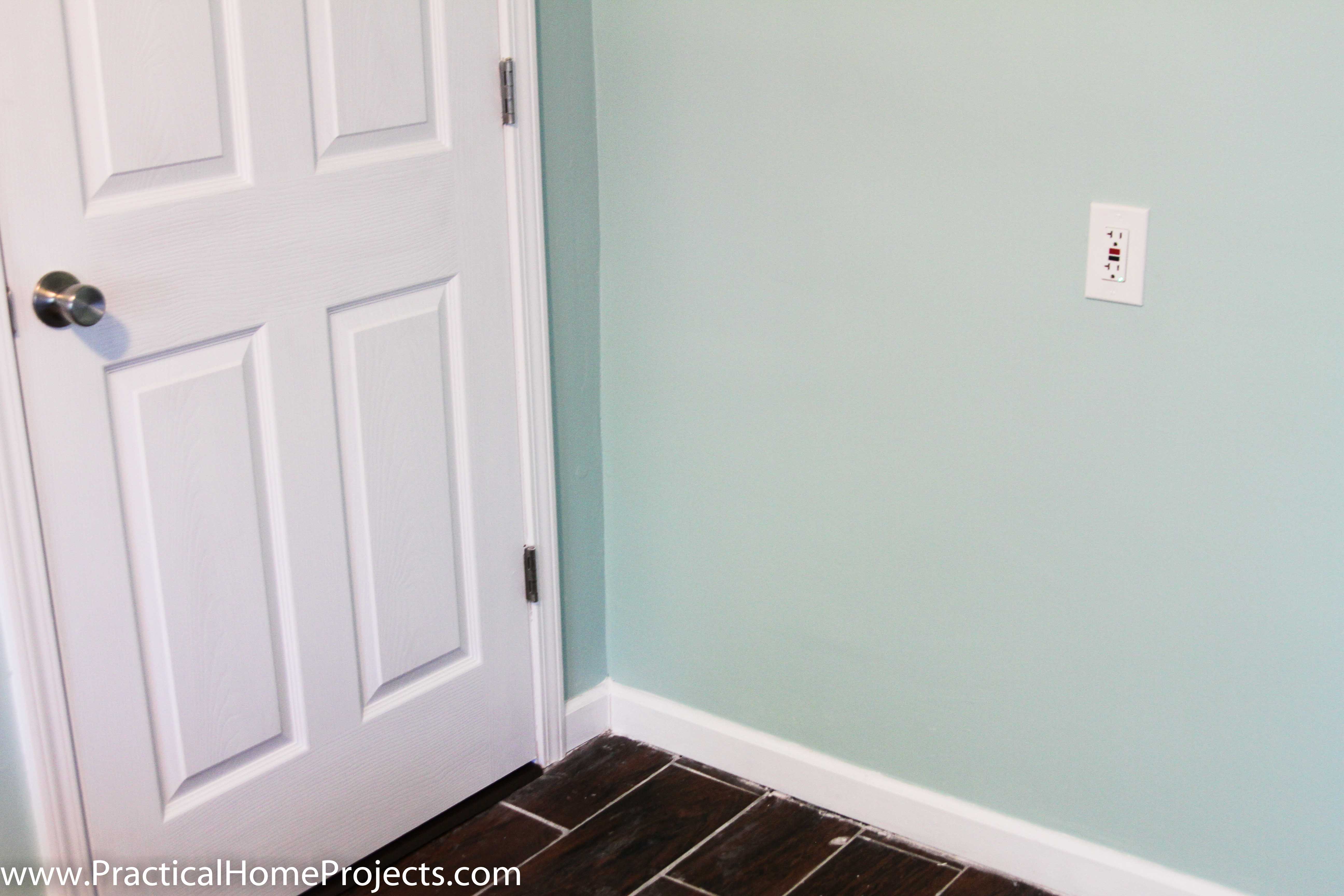
This innocuous little outlet on the wall was my inspiration for this article. It appears to be in perfect order on the surface and the outlet indicator shows that it is wired correctly. After living here for several months, I happened to pop open the faceplate and realize that there were a number of mistakes and hazards just at this one outlet.
I’m an avid fan of fix-it-yourselfers, but this work shows that one DIY enthusiast didn’t do his homework and could have seriously injured someone. Since the error was due to an unapproved modification, the insurance company is not going to want to pay out either.
Below are a few shortcuts that I’ve seen in real life (most in my own home) that are unsafe and unwise. To protect yourself and your loved ones at home, please avoid these mistakes.
1. Shoving multiple cables and wires into the same opening or connection
For starters, keeping your cables and wires separate will make all of your work much easier and less prone to issues. Almost all clamps for junction boxes or panels are meant for a single cable. Only use a single cable per opening so that it will be possible to remove it without disturbing the rest of the connections.
Each Receptacle and switch has a number of screws for wire connections, while each screw is only designed to hold a single wire. Multiple wires will make it much more likely that the connection becomes loose and causes a potential arc fault (resulting in a fire). If you need to bond several wires, use a pigtail to join the wires, then connect to the appropriate screw.
Outlets conveniently have two screws for hot and neutral, but only one for ground. This makes it possible to use the device as a junction for those active connectors, but why is the ground terminal different? If the outlet were to fail at the ground terminal, we wouldn’t want all of the receptacles down the circuit to lose their grounded safety feature.
Similarly any spot on your breaker or the bus bars should be used for a single wire. While it may be legal in some instances, it is not the best practice. If you find yourself out of space on the neutral or ground bar, there is usually a place to add additional bars in your panel. Another option is consolidating a few circuits or upgrading your entire panel. If you combine circuits, make sure that your expected load doesn’t go over the maximum capacity of the breaker.
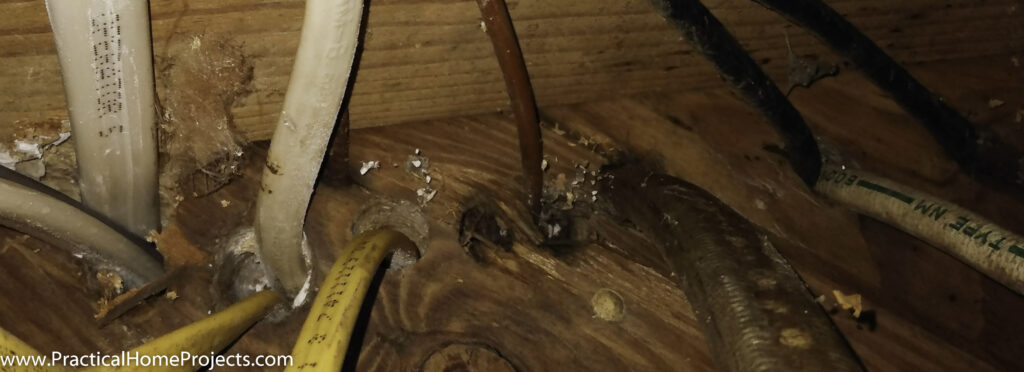
In my crawlspace just below the main panel, lots of wires all come through the floorboards and there is a risk of cables rubbing each other and damaging the sheathing.
There’s no requirement to limit the number of cables going through holes in your studs, but running multiple cables is likely to cause cable burn; moreover, leaving damaged cables is a code violation. Just drill a new hole for each cable one on top of the other. There are two main points from 300.4(A) to think about when it comes to drilling studs: a) don’t cut out more than you need in the stud (¾” hole in a 2×4 is standard) and b) if you drill closer than 1¼” to the front face or notch out the wood, you need a nail plate to prevent someone from puncturing the cable with a nail later on.
2. Not using approved connectors on every splice
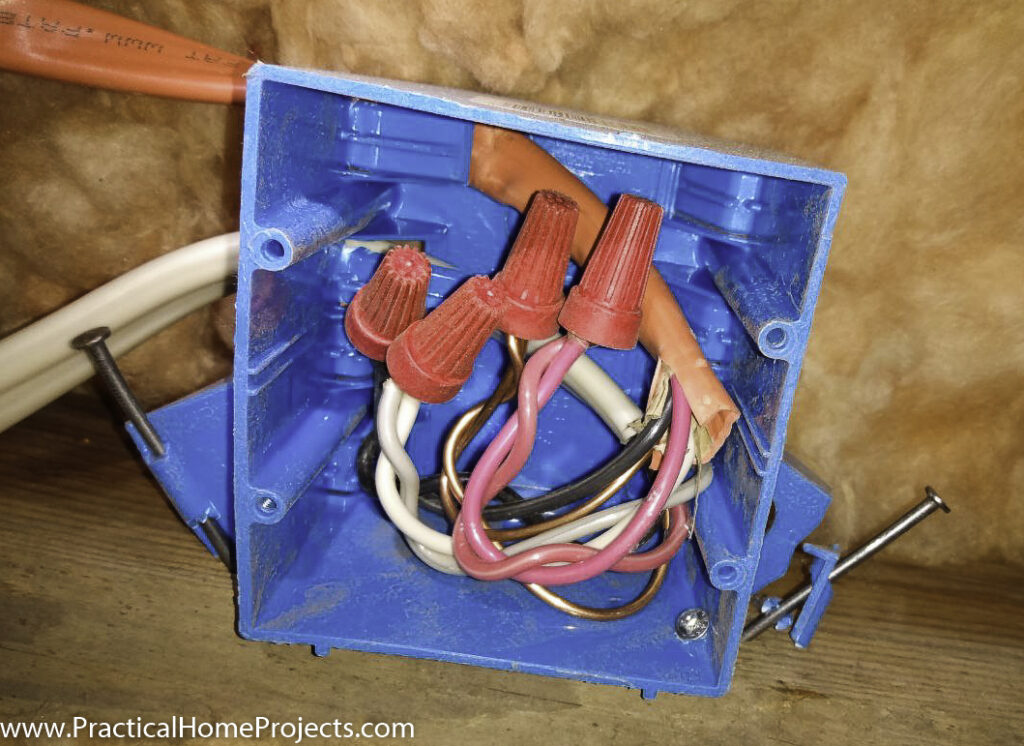
Every connection is required by code to be connected by sufficient mechanical means. Use wire nuts, Wago connectors, or push connectors with every splice. There are two reasons for using these connectors: 1) To cover the exposed ends of live conductors, 2) To provide a reliable mechanical bond between the wires. These UL approved connectors apply enough physical pressure to create a wide contact surface that is resistant to physical or chemical separation.
There are some DIYers or shortsighted electricians who simply twist the wires together in a pigtail and wrap some electrical tape to cover the ends. I’ve particularly seen this shortcut used with grounding wires. This connection is not secure enough and is likely to eventually become loose and cause an arc fault. The reason is because over time the copper wires expand and contract as well as oxidize on the surface. Even though it looks like the wires are in good contact, at the micro level there is an airgap that causes the copper to oxidize. Oxidized copper can take a white or green hue and will cause your connections to fail.
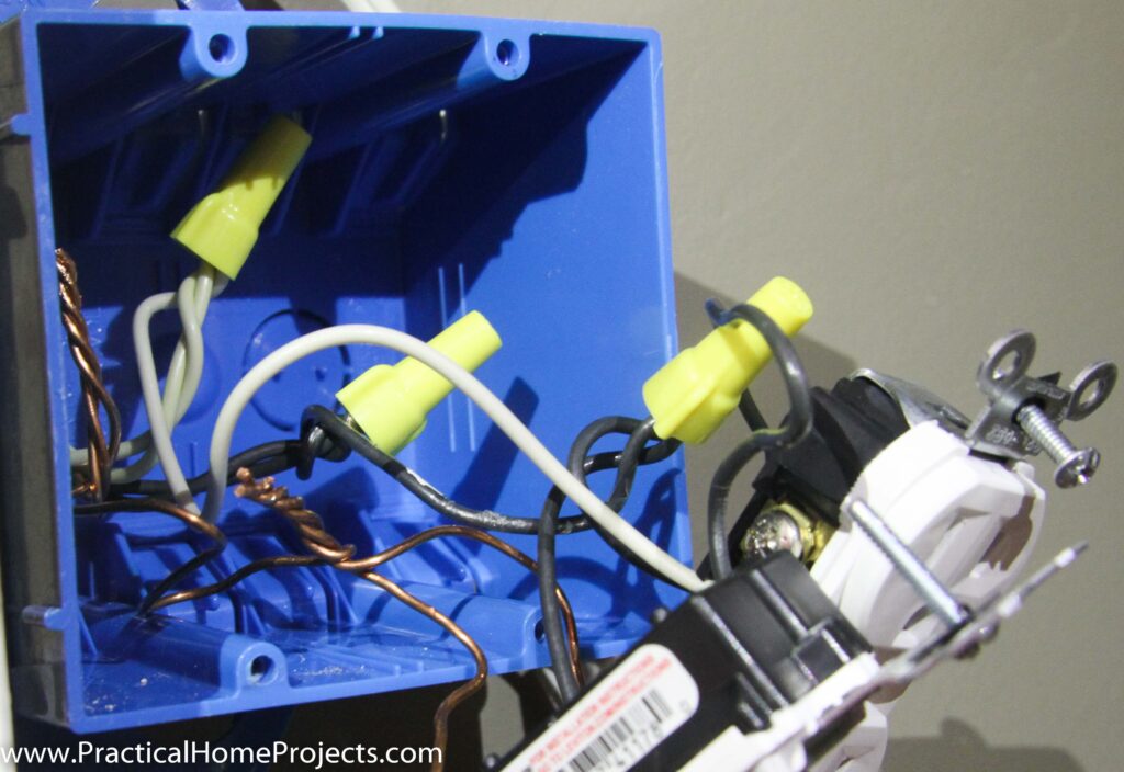

We combined two ground splices into one and put a cap on it. Generally it is best practice to keep all of your grounds on the same connector to minimize risk in the case of a ground fault event.
Wire nuts are the most common connector because they are cheap and reliable. Push connectors and Wago connectors are alternatives that are easier to use and can allow you to work with shorter sections of wire. One major benefit of the Wago connectors are that they are easy to remove. See this [attach article link] article for learning all about wire connectors.
3. Cramming too many wires into a small box
On my shed project, I had cables for two lights, a fan, and the power source entering the same junction box. Rather than shove all of it into the ceiling fan junction box, I added a double gang junction above the rafters to sort out the connections.
In general, a single gang box is good for one receptacle or switch and two cables. If you need to make several splices, use a bigger box. Newer plastic junction boxes tend to be larger than those used before 1980, so simply upgrading could give you enough space to work. See NEC code Table 314.16(A), 314.16(B) in Appendix for other situations.
Here are a few example boxes and sizes:

4. Making a wire connection out of a box or behind drywall
One of the first horror stories when moving into my fixer upper was opening up the drywall and seeing wires twisted together dangling amidst the insulation.
This is a huge mistake for two reasons:
1) It’s a fire hazard having an exposed electrical connection adjacent to combustible materials.
And 2) it’s nearly impossible for anyone in the future to discover since it’s hidden behind drywall.
If this splice were to disconnect (and didn’t burn the house down) I’d have to cut out a ton of drywall before I was able to find it. We ended up putting an outlet in the middle of the wall, then routing that circuit to an exterior outlet.
The other options for this scenario are to follow the cable back a few more feet and put the outlet down lower. Or completely disconnect this end of the circuit from the nearest junction box or panel. Do not ever drywall over a junction box or splice outside of the box!
5. Cheating the tester by connecting ground and neutral
So here’s the outlet we saw in the beginning of the article that appeared to be totally fine. It turns out that someone had wired the receptacle to cheat the tester into thinking that there was a ground connection.
Beginning in 1968, the NEC code required that all new electrical wiring be grounded. There is still wiring out there that is ungrounded and perfectly acceptable, however the appropriate receptacles and markings should be used.
If a cable entering the junction doesn’t have a ground you have 3 options:
- Rip out the wiring and install a romex cable with ground.
- Install a two pronged receptacle so there is no accidental use of 3 pronged device. Most of the devices in your house have two pronged plugs because they don’t require a ground anyway.
- Install a GFCI receptacle with an open ground and add a sticker stating “No Equipment Ground” The GFCI will help prevent any potential electrocution due to missing ground because it will kill the circuit if it detects any current leaving the receptacle and not returning.
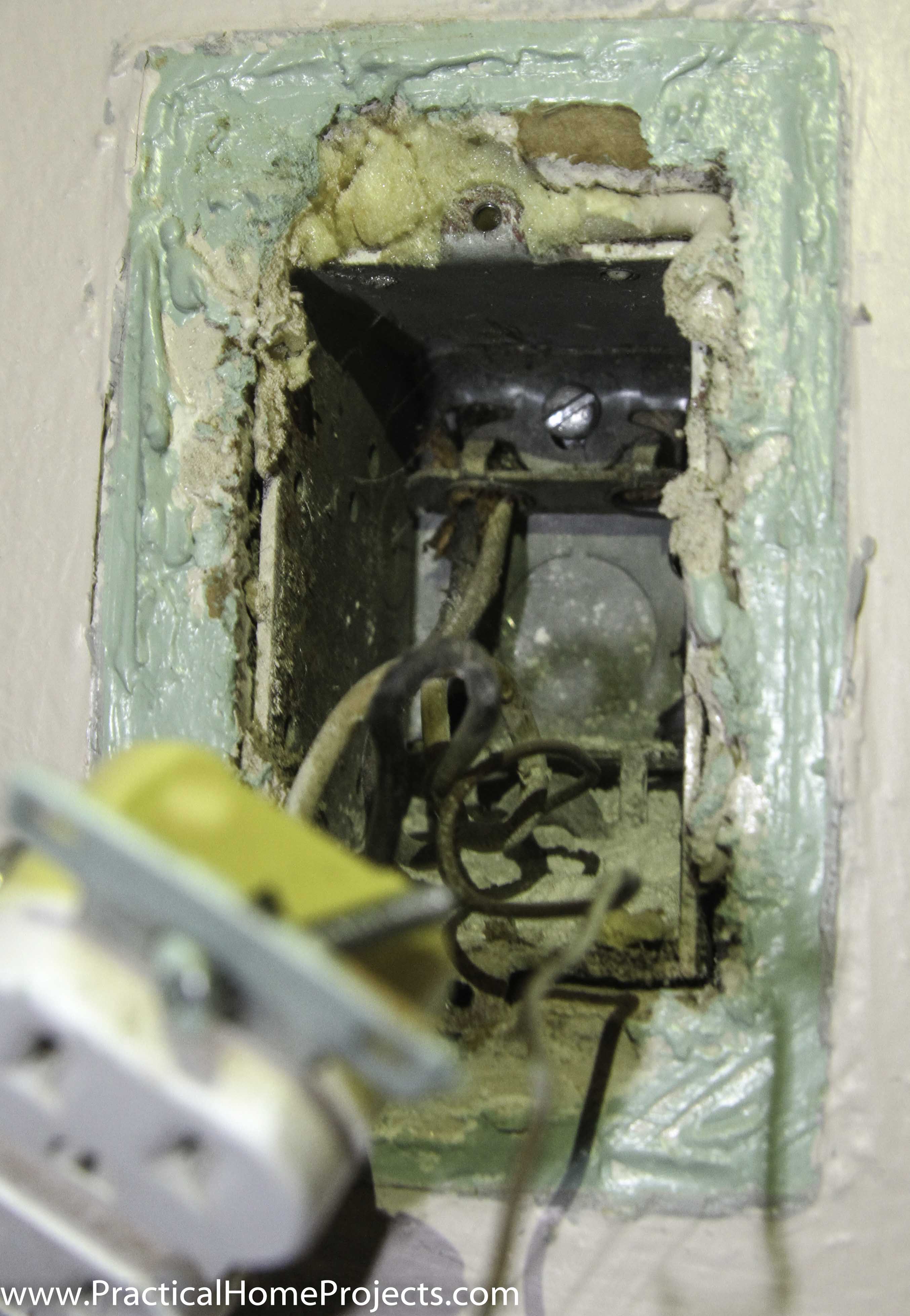
In this outlet, there is a “ground” wire coming from the other side of the box. Apparently it doesn’t connect back to the panel, so they connected the ground and neutral terminals to give the illusion of a grounded outlet.
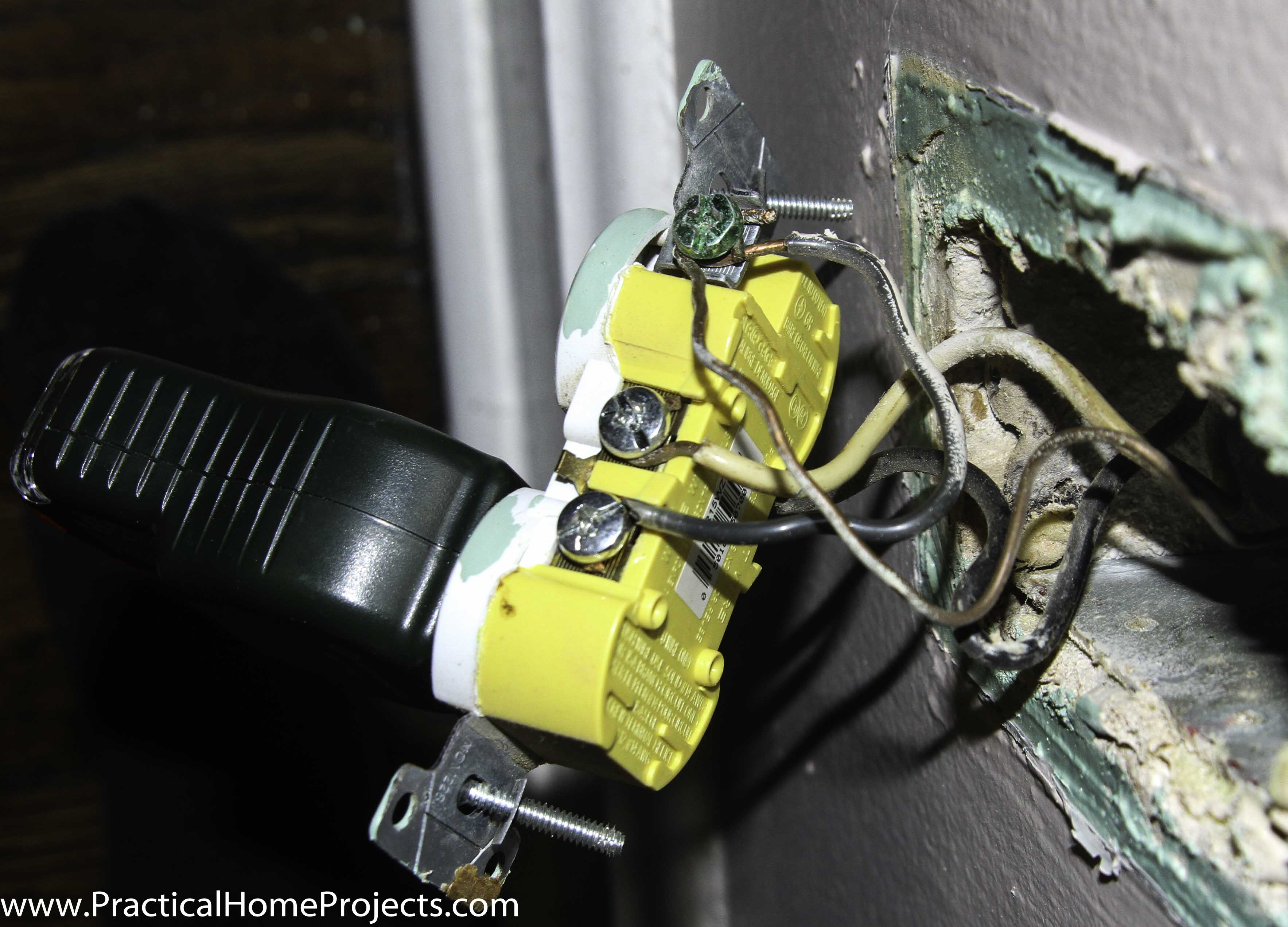
Installing a 3 prong without a ground, or even running a separate ground wire are not code approved, and absolutely do not connect the ground with the neutral on the outlet body! An unscrupulous electrician might do this to give the impression of having a grounded receptacle. If an inspector plugs in a simple outlet test meter, it will read as being wired correctly. This is because the ground and Neutral are bonded together in the main panel.
The grounding exists for when something goes wrong, and by tricking the meter you have not only masked, but AMPLIFIED the risk!
I saw another article where they suggested running a wire from the outlet to a galvanized water pipe because, “the pipe is connected to the ground. Needless to say, such a gross misunderstanding of how electricity works could lead to bodily harm. If you have metal pipes in your house, it is actually a code requirement to connect them to ground in your panel. This is just in case a loose wire in the wall touches the pipe, the current can find its way back home.
Take this terrifying scenario for example. Someone had connected the ground and neutral terminals to cheat the tester on a receptacle as seen in the image. Later on, a refrigerator is plugged into that receptacle. Having a ground is great for the fridge because the compressor can potentially create static electricity or one of the various electrical components could touch part of the framing.
As a safety measure the entire refrigerator body as well as the casing for internal electrical parts are all bonded together and connected to the grounding wire. If for some reason, the neutral becomes disconnected either in this box or a previous one, now the entire current of that device is running on the outside metal body of the fridge! If someone barefoot were to touch the fridge at this point, their body could short the entire circuit and they might die from the electric shock.
6. Using the wrong wires with your breakers
98% of the time it’s easy to put the right wires with the right breakers. 14AWG with 15 amp, 12AWG with 20 amp, etc. If you ever see a thick gauge wire with a low current breaker. Leave it! There is probably a wire or device later on in the circuit that is not rated for the higher current. If a breaker in the house is regularly tripping. Increasing the breaker size does not solve the problem, it merely bypasses the safety measure and could burn your house down. Try plugging your devices into different outlets, get modern energy efficient devices, or as a last resort, run a new circuit.
One seemingly harmless shortcut is using a thinner gauge wire to complete the pigtails. If you used 12 AWG wire on your 20amp circuit, don’t cheat at the final 6 inches and add a 14AWG pigtail. There is a slim possibility of having a problem, especially if you use a 15amp outlet, but if there is an overcurrent issue, your pigtail wire just became the weak point and may burn up instead of allowing the breaker to trip.
7. Leaving a gap between the box and faceplate
The last hack that will come back to bite you is hiding behind that beautiful new tile backsplash. Generally, junction boxes are attached to the stud, so if a new surface covering is added, it’s not feasible to move the box as well. So, the edge of the box is going to be tucked behind that backsplash or panel covering and the faceplate is going to mask the sloppy craftsmanship. Code 312.3 requires that there be no more than ¼ inch gap for non-combustible materials and 0 gap for combustible materials. A loose wire could slip in the gap, or if the face plate were also not firmly attached someone could be electrocuted or the heat from the inside of the box could start a fire.

In my kitchen, the remodeler not only added a tile backsplash, they also added a layer of plywood and drywall to help mount the upper cabinets. The gap from the front of the box to the surface is over two inches!
There are a few solutions here. A simple box extender like this one works well. Or you can try to move the box itself. I love this style of junction box, since you can easily move it again after you install the wall covering so there’s not as much pressure to get the depth exactly right.
You don’t have to use the mounts that come with the junction box
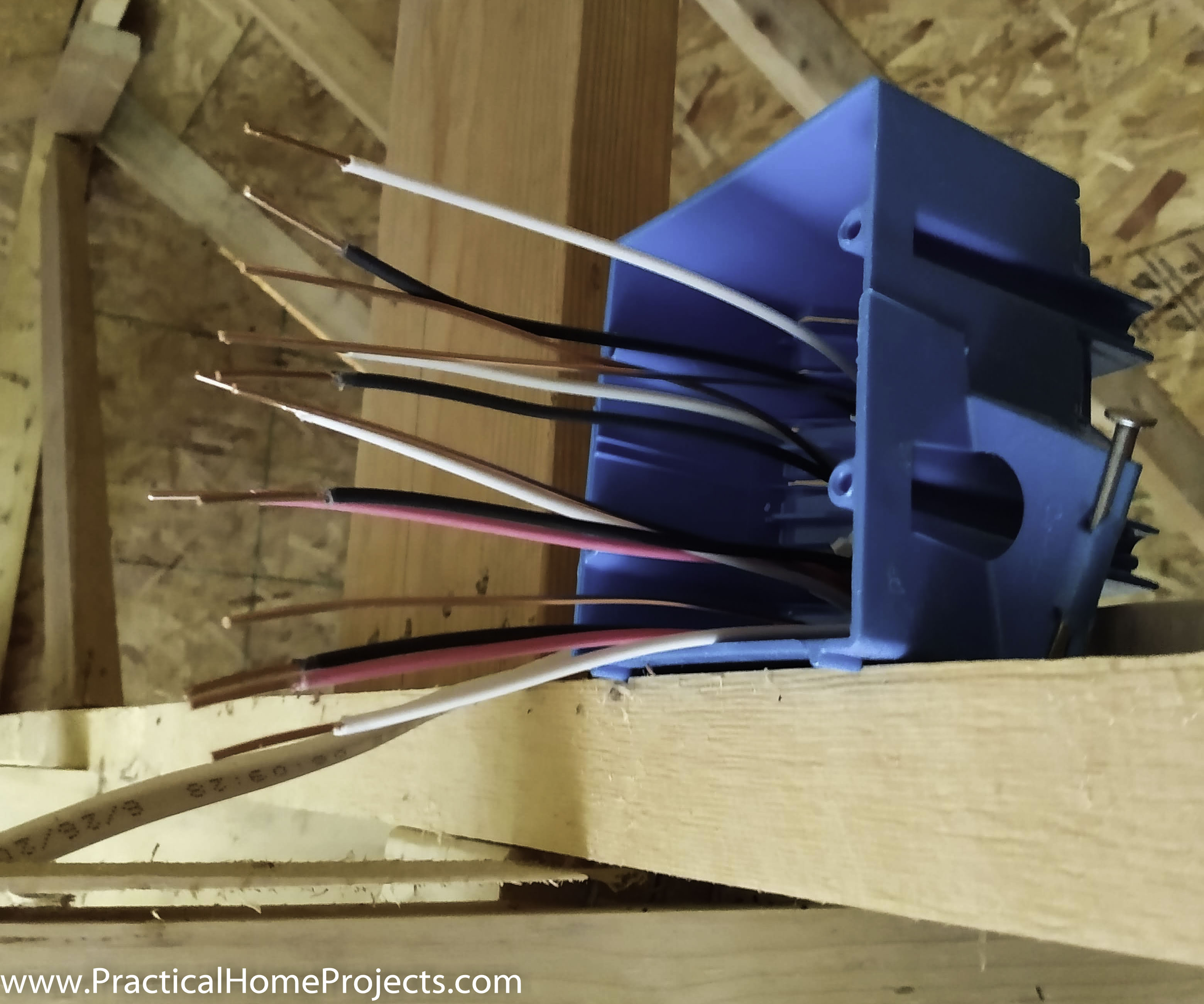
Here’s a shortcut that you can take and it will definitely get you out of a bind. You don’t have to use the mounting tools that come with the box. You’ve seen junction boxes with all kinds of attachments such as nails on the sides, screws on the inside, or a plate to wrap around the stud. The code is pretty lenient about the mounting method as long as it’s sturdy.
In one case, I broke off the cheap plastic bracket holding the nail to this double gang box. Running a screw through the interior wall of the junction box to attach to a stud is a legal maneuver. The NEC 314.23 requires that any screws on the inside of the box have their threads appropriately covered to prevent abrasion.
APPENDIX: All code references are from NEC 2017
312.3 Position in Wall. In walls of concrete, tile, or other noncombustible material, cabinets shall be installed so that the front edge of the cabinet is not set back of the finished surface more than 6 mm (1 ∕4 in.). In walls constructed of wood or other combustible material, cabinets shall be flush with the finished surface or project therefrom.

314.23 Supports. Enclosures within the scope of this article shall be supported in accordance with one or more of the provisions in 314.23(A) through (H).
(A) Surface Mounting. An enclosure mounted on a building or other surface shall be rigidly and securely fastened in place. If the surface does not provide rigid and secure support, additional support in accordance with other provisions of this section shall be provided.
(B) Structural Mounting. An enclosure supported from a structural member or from grade shall be rigidly supported either directly or by using a metal, polymeric, or wood brace.
(1) Nails and Screws. Nails and screws, where used as a fasten‐ ing means, shall secure boxes by using brackets on the outside of the enclosure, or by using mounting holes in the back or in a single side of the enclosure, or they shall pass through the interior within 6 mm (1 ∕4 in.) of the back or ends of the enclosure. Screws shall not be permitted to pass through the box unless exposed threads in the box are protected using approved means to avoid abrasion of conductor insulation. Mounting holes made in the field shall be approved.
(2) Braces. Metal braces shall be protected against corrosion and formed from metal that is not less than 0.51 mm (0.020 in.) thick uncoated. Wood braces shall have a cross section not less than nominal 25 mm × 50 mm (1 in. × 2 in.). Wood braces in wet locations shall be treated for the conditions. Polymeric braces shall be identified as being suitable for the use.
(C) Mounting in Finished Surfaces. An enclosure mounted in a finished surface shall be rigidly secured thereto by clamps, anchors, or fittings identified for the application.
(D) Suspended Ceilings. An enclosure mounted to structural or supporting elements of a suspended ceiling shall be not more than 1650 cm3 (100 in.3) in size and shall be securely fastened in place in accordance with either (D)(1) or (D)(2). (1) Framing Members. An enclosure shall be fastened to the framing members by mechanical means such as bolts, screws, or rivets, or by the use of clips or other securing means identified for use with the type of ceiling framing member(s) and enclosure(s) employed. The framing members shall be supported in an approved manner and securely fastened to each other and to the building structure. (2) Support Wires. The installation shall comply with the provisions of 300.11(A). The enclosure shall be secured, using identified methods, to ceiling support wire(s), including any additional support wire(s) installed for ceiling support. Support wire(s) used for enclosure support shall be fastened at each end so as to be taut within the ceiling cavity.